Repairing a NuTone Model 2067 - 2068
NuTone Transistor Music-Intercom
Models 2067-68
A Centralized System With Room-Selectors
At The Master For Up To 10 Stations
FM-AM Models 2067-68
3-WIRE TRANSISTOR SYSTEM
Never before . , so many features in a luxury set, at a budget price!
NuTone's “Centralized” systems offer you complete control over the entire system from the Master Station. New All-Call Lever at the Master lets you “page” every room with speakers at the same time. Each person can answer, without walking to their remote-speaker to operate the controls.
OUTSTANDING FEATURES
“Local-Distance” Switch for the best reception of distant and local stations – Adjustable, automatic Intercom-Override – 19 Solid State Components – Phono-Jack – AFC – 7” x 5” ceramic magnet speaker in Master – Uses no more current than an electric clock.
The NuTone Model 2067 (Egg-Shell White) and 2068 (Colonial Copper) were introduced in 1965 and it was NuTone's first new Transistor Design since the 2561- 2562 which was introduced in 1957. In 1965 there were still two Vacuum Tube Models in production, the 2055 – 2056 (FM-AM) and the 2053 – 2054 (AM only).
The 2067 – 2068 was an interesting design. It's a very good example of a proper transition from vacuum tubes to solid state transistor designs. The 2067 – 68 shares many design features which were commonly used in early vacuum tube models. It's powered by a 110 volt socket in the wall housing (with a safety disconnect) and incorporates a low-voltage transformer in the chassis which powers the Master Station. It uses audio output isolation transformers and it's a 3-wire system design that will work with all of the previously made NuTone 3-wire remote speakers.
NuTone even sold a Conversion Kit (Model #409) which allowed owners of Models 2011 – 2012 and Models 2015 – 2016 to convert their Master Station to the new 2067 – 2068. The conversion kit only cost $2.95 in 1966. All of the other NuTone Vacuum Tube Systems could be converted without using the Model 409 kit.
In the 1966 NuTone Intercom Catalog, NuTone started to uses terms like “Wide Range” and “Hi-Fidelity” when describing the Remote Speakers for the 2067 – 68. Since the 2067 – 68 uses exactly the same models of remote speakers as the other 3-wire systems, these terms were somewhat marketing on NuTone's part, although since the sound quality of the Master Station was improved, the speakers could take advantage of that improvement.
In 1966 the 2067 – 68 Master Station had a list price of $152.00 which placed right between the 2561 -62 ($185.20) and the vacuum tube Model 2055 – 56 (131.70). NuTone offered a suggested Basic System Kit, which included a Master Station, 3 Room Stations, a Front Door Speaker and 200' of 3-conductor wire for $195.40. It's unclear if this kit included the Rough-ins for the system or not.
The 2067 – 68 is always a good candidate for repair. It is well constructed with one major exception, the Plastic Faceplate.
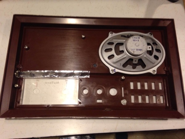
I'm not sure what type of plastic NuTone used for the molded faceplate on the 2067 – 68, but it has to be one of the most brittle types of plastic that exists. I don't think that the brittleness of the plastic is due to aging. I remember when these models were around 20 years old and the face plates were just as brittle. It is extremely easy to snap off a piece of the faceplate edge by just twisting it too hard or bumping it into something. For this reason, if this model is being shipped in for repair, the chassis must be removed from the faceplate and be shipped by itself.
Removing the chassis from the faceplate is very easy. It's held in place with 4 screws and even the wires that are connected to the speaker cone are connected with screws. After removing the chassis, be sure to put the faceplate in a safe place until you get the repaired chassis back.
Common problems with the 2067 – 68 are very much like all older NuTone designs. Failing capacitors in the power supply and in the amplifier impact the overall quality of the sound and operation of the system.
Since the 2067 – 68 is an early Solid-State design, it used “old-school” components, which are of different values and design than modern components. It's important to use the correct components throughout the Master Station to insure its proper operation.
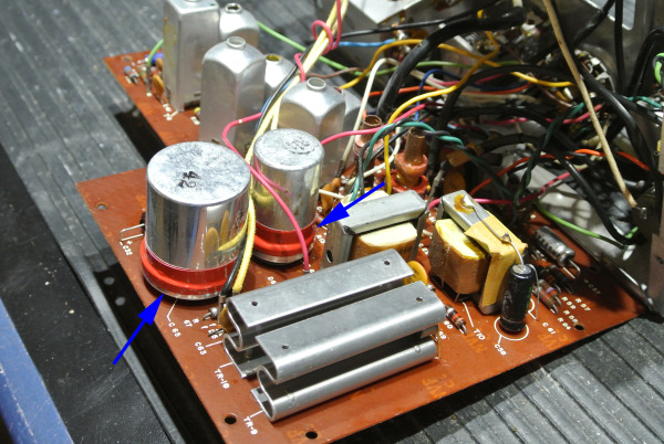
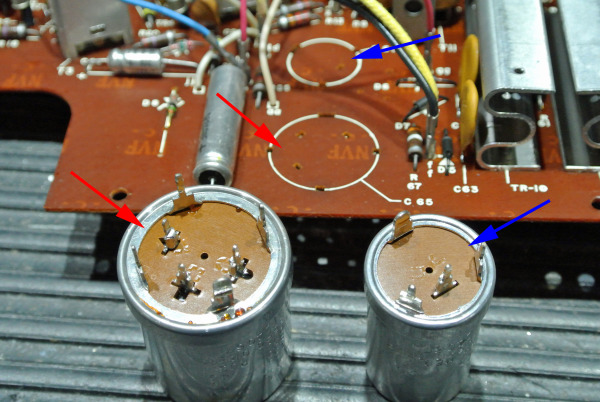
Sometimes there has to be “exceptions” to this rule. In the 2067 – 68 there is a Multi-Section Can Capacitor and a Single-Section Can Capacitor which will need to be replaced.
The Single-Section “Can” is somewhat of an odd choice in this design. It contains a single-value capacitor and it would have been easy to use a standard part in the design. The “Can” was probably used either to speed assembly of the chassis or because it was being used in other models, so it saved on cost.
The proper way to replace these “Can Capacitors” is not to replace them (since they are no longer available in the correct values), but to rebuild or “re-stuff” them.
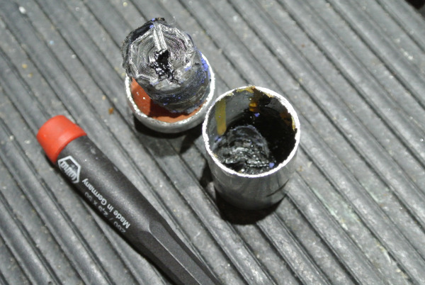
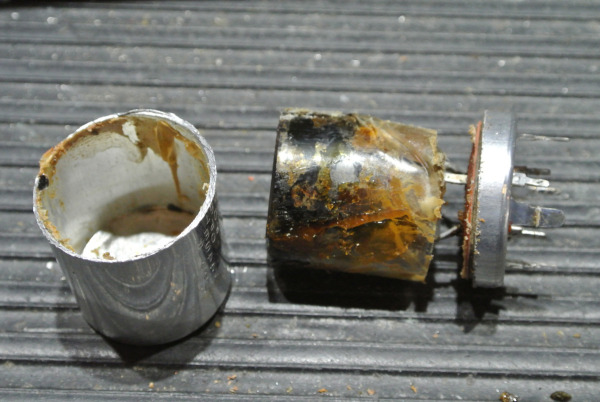
The can is removed for the circuit board and it is carefully cut open around its base.
Inside is the “jelly-roll” that makes it a capacitor. The jelly-roll is made up of 3 layers:
-
A thin sheet of aluminum foil
-
A thin sheet insulating material (waxed-paper)
-
A thin layer of electrolyte
The 3-layers are rolled up very tightly and connections are attached at each end. Then the roll is inserted into the can and sealed up.
A Multi-Section Can Capacitor can have between 2 and 4 capacitors inside the Roll. This is accomplished by adding connections not just the the ends of the rolls, but throughout the roll itself, dividing it into “sections”. Each section has a different value, which creates a different capacitor.
To maintain the integrity of the design and for best operation, new modern capacitors should be mounted inside the original can.
After the can is cut open, the roll can be removed. The base should be cleaned along with the inside of the can. Sometime the can will have a tar like material in it. This should be removed.
On the bottom of the base there will be a variety of connections. Typically there are 3 or 4 tabs around the base on the can. These are all common terminals to each other (either the + or – of all of the capacitors). In the center of the base there will be one connection for each section inside the can.
The goal is to properly mount new capacitors (one for each original section) on the base and still be able to place the cover back onto the base. This is not always easy.
The can capacitors in the 2067 – 68 all have the same value of 500 Mfd, which is an old-school value.
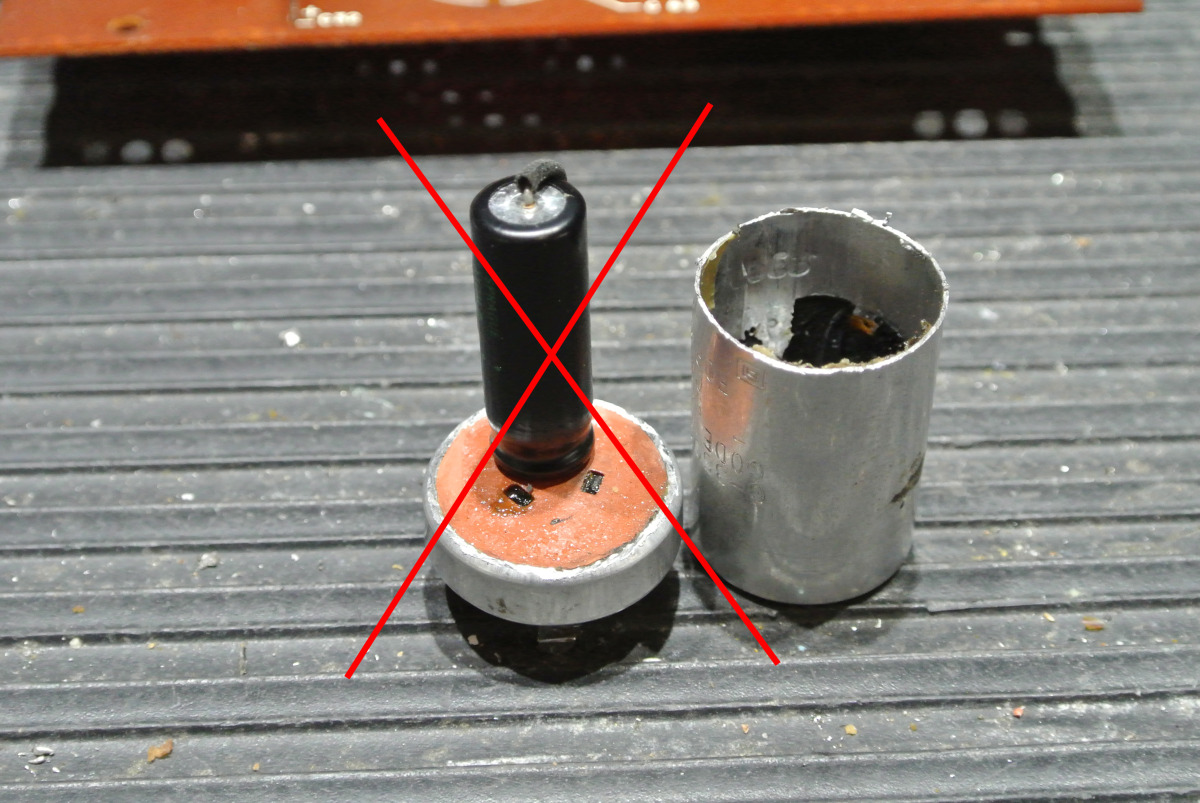
While this type of component is still available in limited choices, the part was too tall to fit inside the can properly.
Modern capacitors are typically small, but the values are different. The closest choice to the original value of 500 Mfd is 470 Mfd, which is not close enough for me.
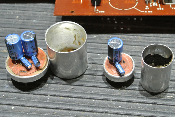
The best solution is to double up 2 capacitors for each section (470 Mfd + 33 Mfd = 503 Mfd). With a little bit of effort, it's quite possible to have everything workout well.
So, why is this so important to do? Two reasons. Generally can capacitors will share either a common positive or negative terminal for all of the sections, which will be the “can” terminals. If you tried to mount 2, 3 or 4 separate parts on the board (in place of the actual can), it's difficult to have the parts be secure, and you would have to add jumper wires under the board to connect all of the common terminals. This is messy and it will often cause a very noticeable Hum on the system. The second reason is to maintain the originality of the design. When done carefully, most people would never know that the can was modified.
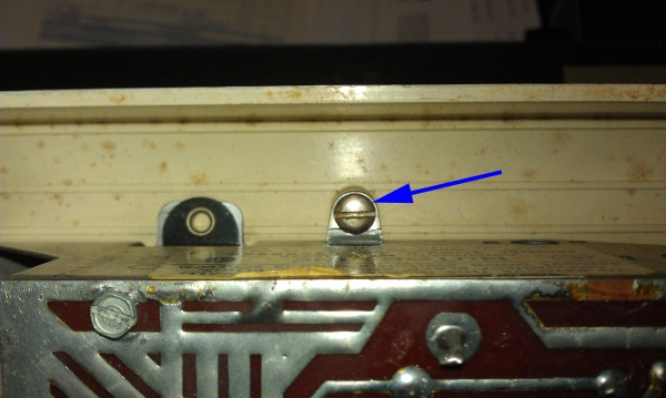
This particular 2068 had an additional problem that was not age-related. It had a broken On/Off – Tone – Volume Control Switch. Someone probably turned the volume control beyond its limit and broke it internally.
When the chassis was delivered to me for repair, only the dial lamps would light up, and there was no sound from the speaker at all. I noticed that the On/Off switch had been by-passed and a toggle switch had bee added to turn the system on and off.
I removed the toggle switch and reconnected the power wires to the original switch, which worked properly. I notice that the range of the volume control was about one-third of what it should have been. Giving it good twist, I was able to move it past the obstruction and there was static on the speaker.
If I turned the control carefully and held it in just the right spot, I could get the radio to play – fantastic.
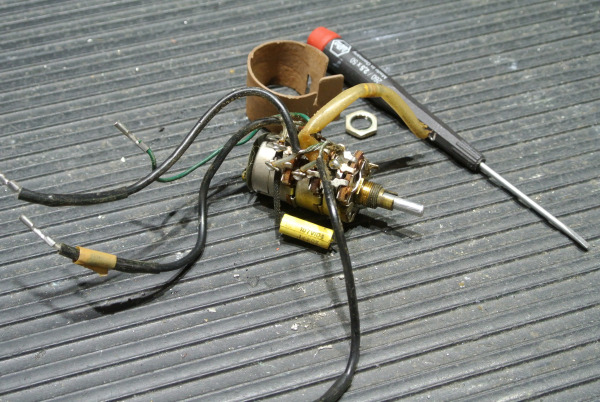
Luckily, I had another “parts” chassis that I could scavenger the switch from. These early models have many wires connected to the switch terminals. It's best to leave these connections alone and disconnect the other ends of the wires from around the chassis.
Once the “new” switch was in place, the set played well. One of the common problems with these early designs is the difference in sound level between the AM and FM tuners. It's not uncommon for the FM sound level to be one-half of the AM level.
This is often caused by “drift” in the FM tuner alignment, although it can be caused by failing components in the FM tuner as well. Working on either AM or FM tuners is a very specialized skill and should not be attempted by anyone without experience. It's very easy to make things much worse and finding your way back to the original starting point can often be impossible.
The end result of the 2068 chassis rebuild was very successful. The “master” played very well and worked correctly.
I made up a custom Audio Input Jack which could be mounted through the hole that had been made for the hacked-in power toggle switch. This was a good way to allow the owner to connect her iPod to the system.
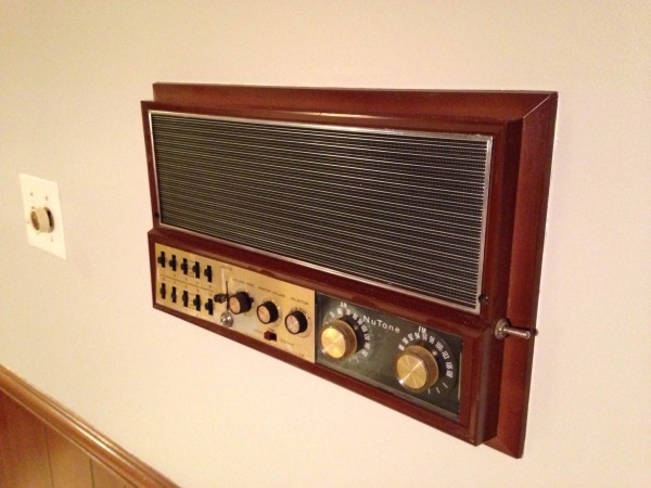
After Jennifer received her 2067 back, she assembled the Audio Jack and remounted the chassis to the face plate. I helped her just a little on the finer points, but she did all of the work. After reinstalling the 2067 she finally had music throughout her newly purchased home. I understand that some of the remote stations required a little attention to make them play again.
 Cindy & Christopher