A somewhat toasty NuTone 2057 / 2058 arrives at the shop
 Thursday, December 6, 2012 at 4:05PM
 I remember when servicing NuTone intercoms with vacuum tubes was still fairly common, but now-a-days it's pretty rare to see these early models.
"A modern design in Copper or Silver Anodized finish with contrasting back border and dial-panel. Separate FM and AM meter-type tuning bands. Transistorized Intercom System with selector-switches for ten stations. Rotary-Controls for volume and tuning, talk-listen switch for door answering are clearly marked. Superior tone for FM and AM radio. Excellent voice-register for Intercom."
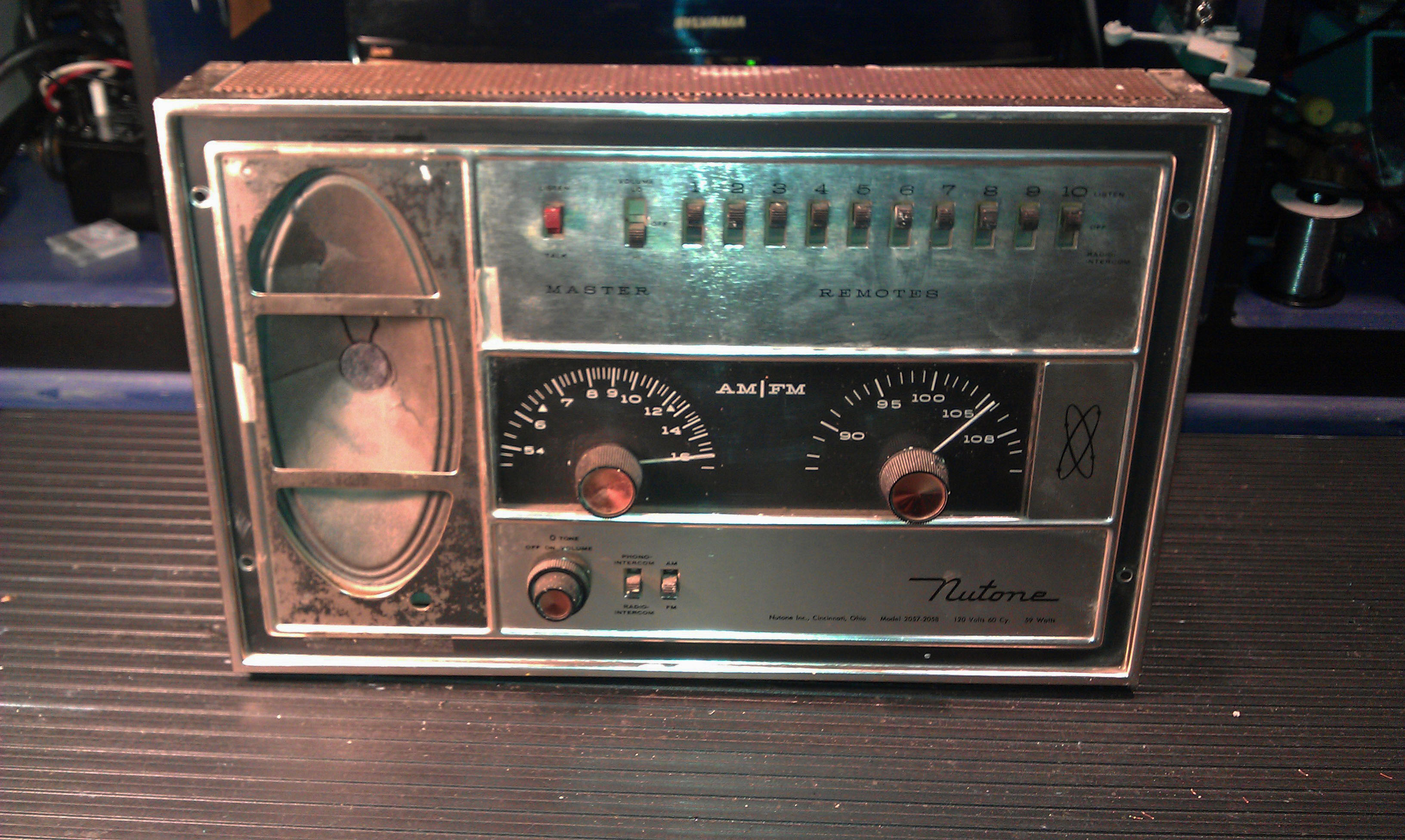
The 2057 (Silver) and 2058 (Copper) was the top-of-the-line model in 1962 and the retail price was $151.50. I think that was a lot of money in 1962.
This 2058 was manufactured in 1962 and it comes from a nice custom home that must have been very swanky for its day.
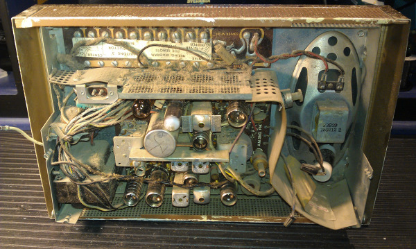
This 2058 has not worked for years and judging by the amount of dirt and dust build up, it may not have ever been removed from the wall housing since the day it was installed.
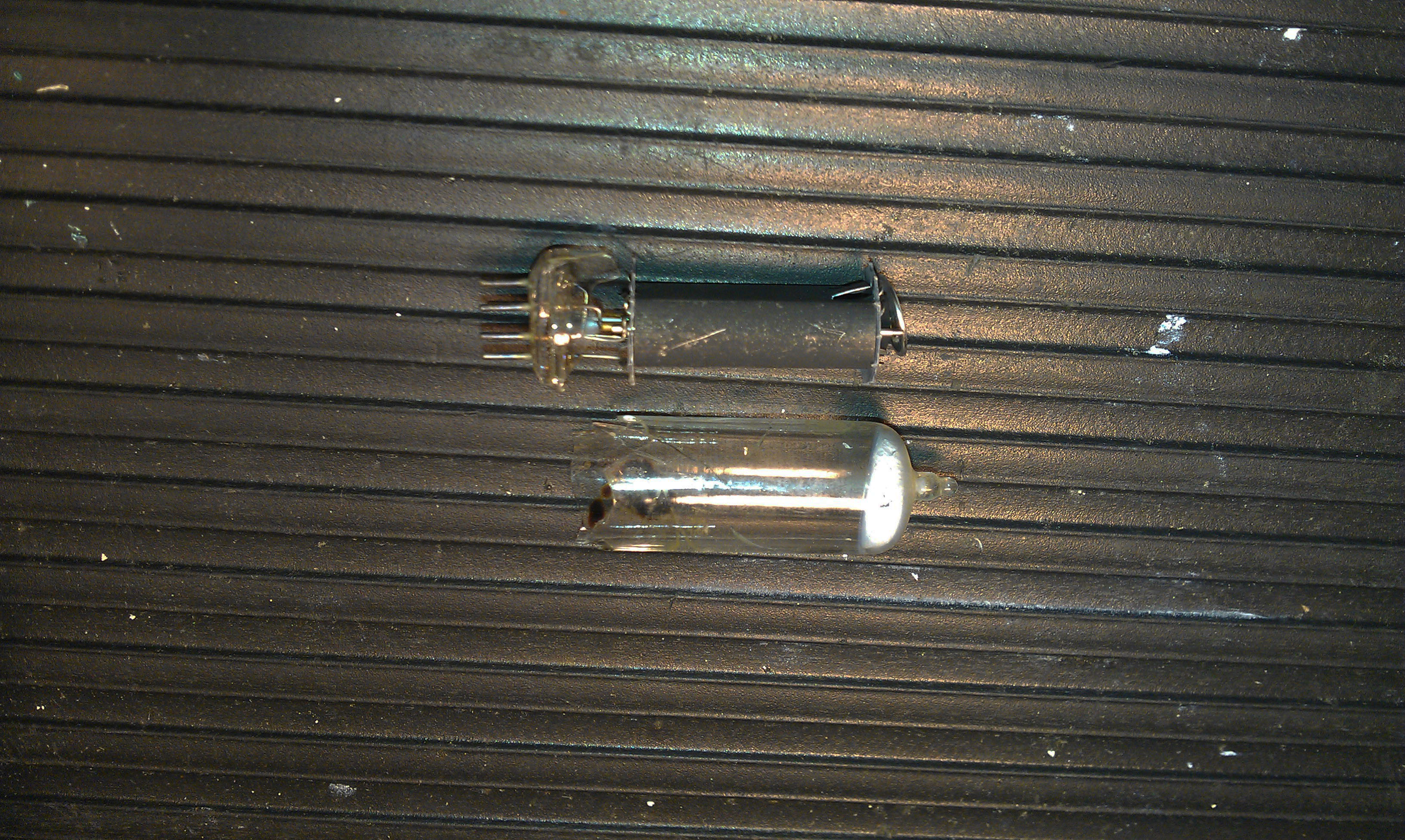
So far I have just cleaned it up enough to begin checking it out. I have found 3 failed tubes and 1 broken tube.
With some thought and effort, this 2058 will play again and add back some of the swankiness to its home.
See all of the 2057 2058 pictures here
 Cindy & Christopher
Saturday was the day to finish up this 2057. With the four replacement tubes installed and the Master connected to a variac and watt meter, it was time to see what condition this 2057 was in.
The variac is used to bring the power up slowly, while watching the watt meter for excessive current draw. This method is used on tube equipment to ensure that if the set is severely damaged powering it up will not make it worse.
It's important to remember that tube sets operate with HIGH VOLTAGE. This 2057 has up to 270 Volts on the circuit board, care MUST BE TAKEN otherwise you CAN GET HURT by this HIGH VOLTAGE.
As I increased the power everything was looking good and after a few minutes I had static and some faint AM radio but no FM. A little poking around seemed to lessen the staic and at one point the FM drifted in, somewhat.
This was a good enough test and I moved on to the next step, disassembly.
I decided that it would be easier to disassemble the 2057 and remove the circuit board from the chassis. This would allow me to clean the board and inspect it.
To remove the circuit board I had to unplug all of the interconnecting wires from their pins scattered around the board.
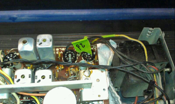
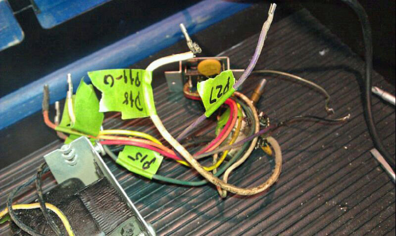
The easiest thing to do is label each wire with its terminal number, so nothing gets mixed up when it's time to reassemble everything.
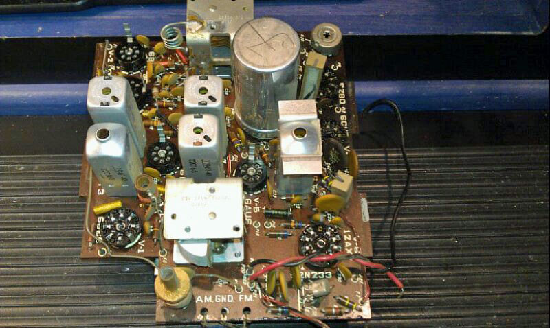
With all of the wires removed and a a few other bits out of the way, the circuit board just lifts out of the chassis.
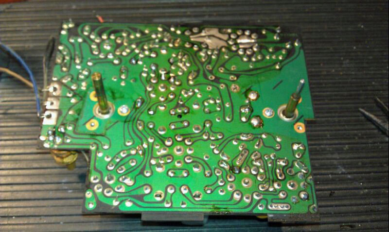
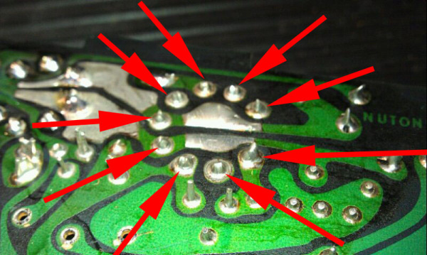
After cleaning the board I inspected the solder side and found many bad solder joints. This was especially true around the EZ80 and 6CU5 tubes. These two tubes are the hottest tubes in the 2057 and the solder connections on the tube sockets had failed due to the exposure to 50 years of heat. This explained the varied operation when I was testing the master.
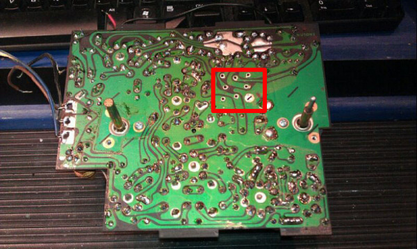
I decided that reflowing every solder joint on the circuit board would be the best way to make sure every solder joint was good. This adds some extra time to the repair, but it's worth the effort to makes sure the set will be reliable.
The area inside the red box is where the main power supply capacitor is located. This is a Multi-Section Can Capacitor and replacing it will be the next step in repairing this 2057.
 Cindy & Christopher
The most difficult component to replace onthis 2057 is the original Sprague multi-section power supply can capacitor. This is a 4 section can capacitor with values of 100mfd @ 250 volts, 2) sections were 40 mfd @ 250 volts and the fourth section was 50mfd @ 25 volts.
These types of multi-section can capacitors use different symbols to identify which solder lug belongs to which section. In this case the symbols were:
Δ = 100mfd @ 250 volts
p = 40mfd @ 250 volts
m= 40 mfd @250 volts
- = 50mfd @ 25 volts
While there are several different companies that manufacture new multi-section can capacitors, none of them had the correct values for the 2057.
I decided that the best method would be to “restuff” the original can with new modern capacitors. Sometimes it's practical to install individual capacitors in place of the original can, however this often looks messy and securing the components can be tricky.
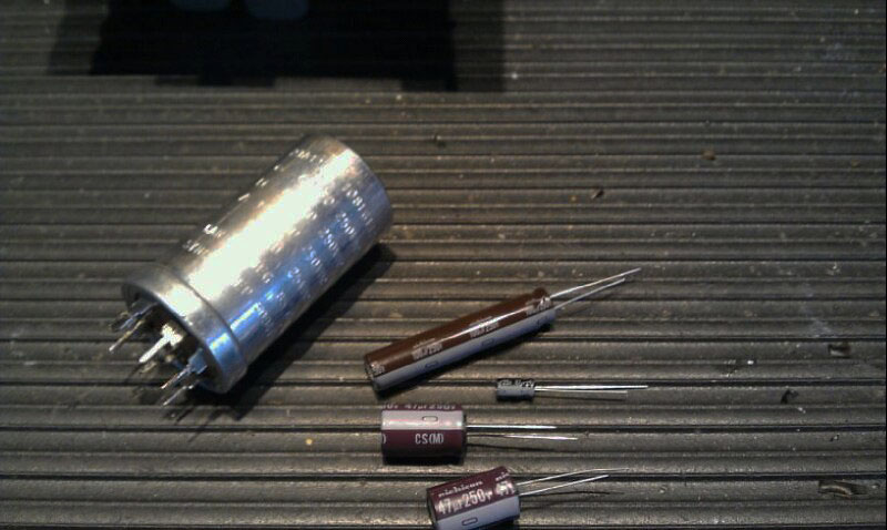
The first step was to search for new capacitors that fit into the 1.5” diameter can properly. I found Nichicon CS Series which are pencil shaped capacitors. This series is a long and thin radial capacitor which only took up a small amount of the available space. I choose two 47mfd capacitors from the same series to take the place of the 40mfd sections. The original 50mfd section was replaced with a 47mfd from a different series, mostly for its small size.
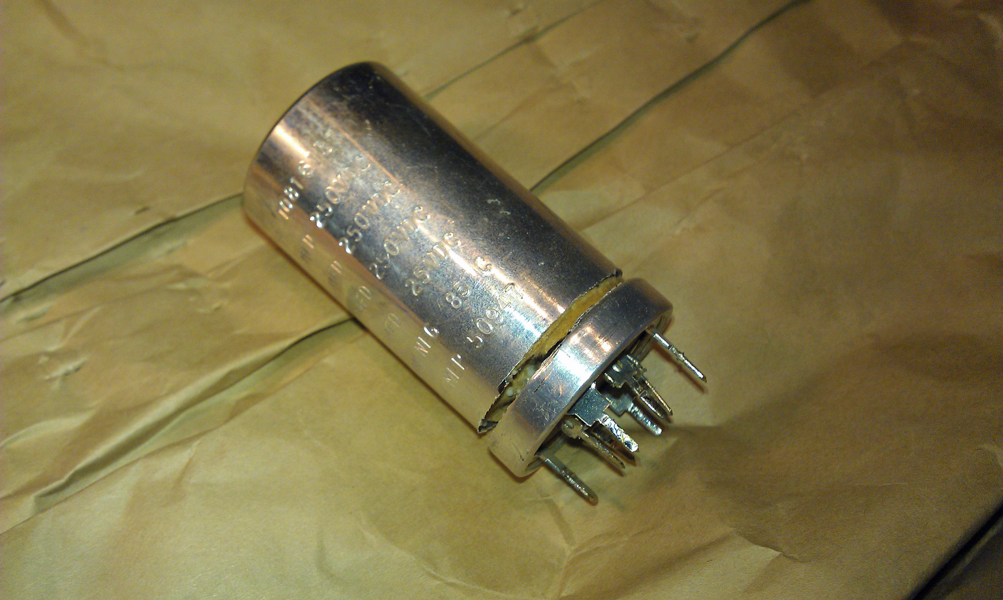
After removing the can capacitor from the circuit board, I took it over to the band saw and carefully cut the aluminum can right where it begins to flair into the larger diameter at its base.
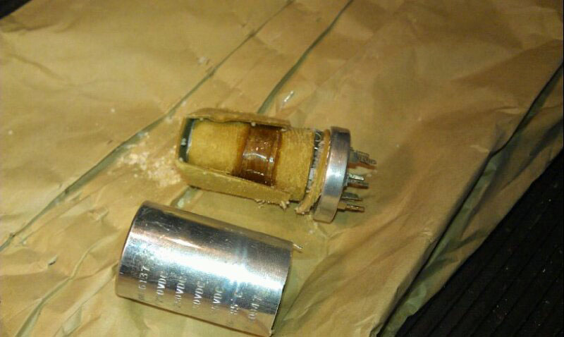
When you pull the cover off, inside you will find the capacitance roll. This is made up of a long thin sheet of insulating paper which has a thin layer of aluminum foil attached to it.
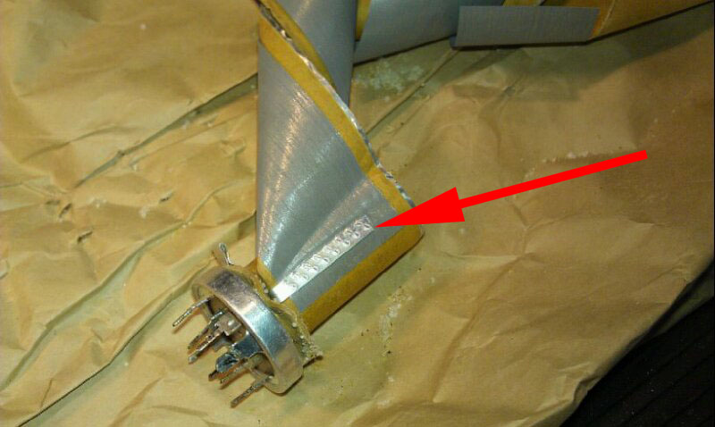
As you unroll the capacitor you will find points within the roll that have aluminum strips fastened to the aluminum foil by some type of crimping method.. These strips are connected to the solder lugs on the bottom of the can.
The more you unroll the capacitor the more aluminum strips your will find. Since this is a 4 section capacitor, there are 4 aluminum strips, plus 1 more which is the common negative and is attached to the can itself.
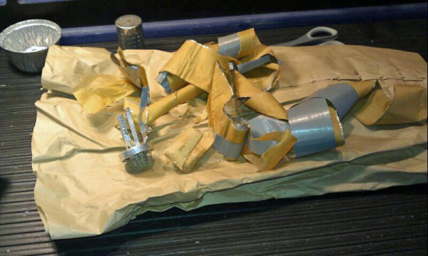
After the entire roll is removed you are left with the cans base and all of the aluminum strips.
It will be necessary to install the 4 replacement capacitors onto the base of the original can. I carefully drilled (8) 1.25mm holes in the original base, 1 along side of every positive solder lug on the original base and 1 along side each of the common ground lugs around the perimeter ring for the negative terminal.
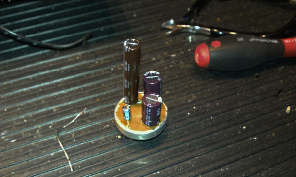
After all 4 of the new capacitors where in place, I used my LCR meter to verify that the each of the new capacitors where in the proper location, referenced by the symbols on the cans cover. I then used a multi-meter to make sure that the common ground was intact on all 4 ground lugs.
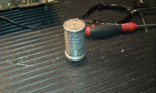
To close up the can, I simply placed the cover back on the base, matching up the cut marks and sealed it first with electrical tape followed up with a section or large diameter heat shrink tubing.
Once the can was remounted on the board, you really couldn't tell that it had been modified at all.
 Cindy & Christopher
The bench repair of this NuTone 2057 took 5 hours from start to finish. This included the time it took to disassemble the master station, perform more cleaning of the chassis, circuit board, faceplate and knobs and repair the torn speaker cone.
The restuffed multi-section capacitor was remounted to the circuit board and the only other electrolytic capacitor was replaced. All of the tube sockets were cleaned as were the control switches.
The paper speaker cone had been torn sometime in the past and there are no replacements available any longer. I inquired with several companies that recone speakers, however the cost was prohibitively expensive for this project.
I decided to use an old trick to repair the tears. I thinned down some Elmers white glue with water and carefully glued the tears back together with a small artists paint brush. After the glue had dried, I made another application tothe back of the tears. After this dried I applied the glue solution to the entire paper speaker cone, especially around the perimeter where the paper fold get quite thin.
While this method of reinforcing the paper cone works well, it does change the tonal quality of the speaekr some, but it's cetainly better than the sound a torn cone makes.
After the entire 2057 was reassembled, I connected it to a temporary power cord and and turned it on. After the warm up period, sound slowly faded in form the speaker and we had radio.
The AM and FM reception was spot on and the sound quality and volume was exactly as I would expect from a 1961 vintage Master Station.
I let the 2057 play for the remainder on the day, checking it periodically for any potential problems and changing stations to check the reception. I noticed that the overall reception quality improved after the master had been on for about 30 minutes.
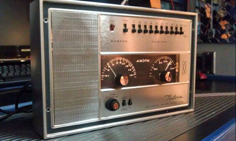
I finished cleaning the faceplate and reattached the grill. I aligned the radio dial pointers to reflect the radio stations being played and installed new tuner dial lamps.
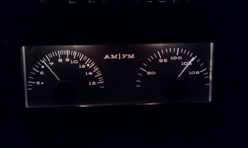
The dial lamps are GE #12 bulbs, which are somewhat difficult to find and not in expensive. As an interesting note, this bulb is also used in vintage Lionel train accessories. I found the best deal for the bulbs at Replacement Light Bulbs.Com.
The 2057 played on the bench for the following week, waiting to be reinstalled back in its home.
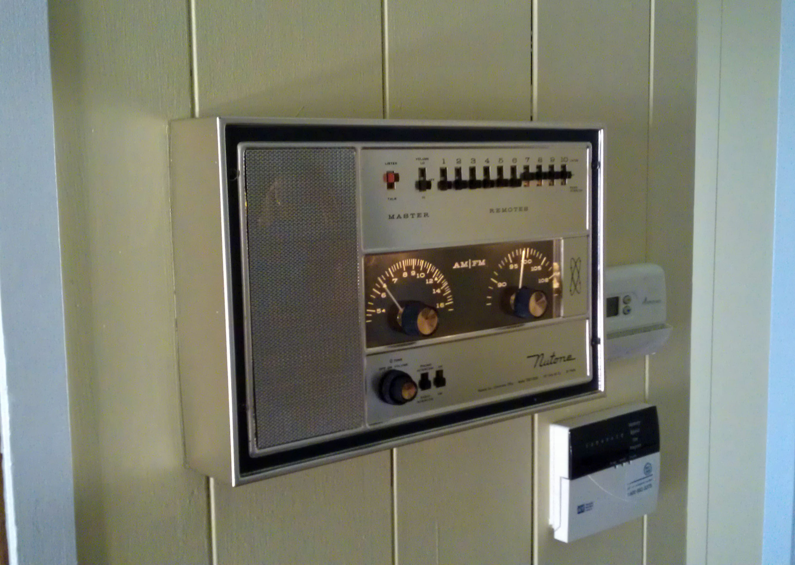
The 2057 was reunited with its system and after just a little general service to its remote speakers everything work correctly and sound very nice.
With just a though and a little work this Vintage NuTone 2057 went from awfully worn and tired to shiny and quite nice looking.
Ask a question about your NuTone Tube Intercom System