NuTone Model IM5006 Selective Call Radio Intercom
NEW! IM5006 Selective Call Radio-Intercom... The IM5006 was introduced in 1991 as the simplified version of the IM6106. The IM6106 was an epic failure and technically it was never released to the public, but that's another story.
You can trace the lineage of the IM5006 all the way back to the 2561-2562 in 1957. The IM5006 is a feature packed Selective Call Radio Intercom system with features like private one-to-one communication between stations, one-button talk & listen, hands-free answering, and it could operate up to 24 remote stations.
The IM5006 was designed to be loop-wired using NuTone IW6 wire. It can also be home-run wired or a combination of both wiring schemes. Most initial problems with the IM5006 were installation related. The IM5006 required a higher level of workmanship when it was installed to have it work properly.
The single most common installation issue was with wire termination; how the wiring was connected to the master station and the remote stations. On the remote stations it is necessary to twist the common colored wires together (red with red) before attaching the wire onto the circuit board. The twisted wires must be placed between the 2 flat washers on the screw terminal standoff, and the end of the wire must be bent around the screw in a clockwise direction. The wire must remain completely between the 2 washers as the screw is tightened, and not be allowed to be squished out as the screw is tightened.
At the IM5006 master station there is a connector on the edge of the main circuit board. This connector is only large enough for 4 wires to fit into each location. If your system has 14 stations, you will never get all of the wires into the connector. In these installations it is necessary to “bundle” the wires together (all reds together, all blacks together etc.) and then add a single extra wire for each color , which is inserted into the connector.
“Bundling” wires will cause many problems if not done correctly. The common method is to use a “wire nut” on the end of each of the different colored wire bundles. This is wrong and will cause problems with the systems operation. The problem with wire nuts is that they primarily twist the outer wires together tightly, leaving the inner wires somewhat loose.
The IM5006 uses digital communication throughout the system and the “loose” wires inside the bundles will cause the digital signal to become lost and the attempted communication will fail. Loose bundles will also cause excessive static on the system and may contribute to failed remote stations.
The proper method for making bundles is to twist each color of wire (red to red) into pairs, then twist the pairs into groups of 4, then the groups of 4 into groups of 8 and so forth until all of the wires are twisted together. Now comes the most important part. All of the bundles must be soldered, which removes any of the microscopic gaps inside the bundles. Now a wire nut can be twisted over the soldered bundle to act just as an insulating cover to the bare wire ends.
As with any excessively complex design, the IM5006 had many service updates during the first year to solve and correct problems that occurred once they were installed in consumer's homes. Most of these modifications were to solve small problems like insufficient volume adjustments, excessive humming noise at the master station, slow running clock and and tuners that did not scan properly.
As these problems were solved, the fixes were incorporated into revised circuit boards on newly produced models. The down side to all of these changes is that there are as many as 7 different circuit board sets for the IM5006 and for the most part the boards for these sets are not interchangeable between sets. As an example, boards from units with serial numbers 101-102 are not interchangeable into sets with serial numbers 109-110.
The IM5006 was originally covered by NuTone's Lifetime Warranty (MPP Warranty) and the usual course of action for a defective master station was to send it back to Nutone's in-house repair center as a complete unit. This way the circuit boards in that actual master would be repaired, keeping all of the boards together as a set.
When NuTone closed its in-house repair facility, it became more important to understand the typical problems that the IM5006 suffers from. The IM5006 has actually been a fairly trouble free model with only a few common problems.
Before I get into the common problems:
A word of warning: The IM5006 is not a model that an amateur should try to repair. The design of the circuit boards is very complex and requires specialized tools and equipment to work on. One mistake can cause the circuit board to be ruined. Since replacement boards are no longer available from NuTone, and the chances of finding the correct series of board used is slim, one mistake can turn your IM5006 master into a worthless and unrepairable unit.
Also, never, never, never disconnect or connect any and remote station from its wiring while the IM5006 is powered up. This will certainly damage the IM5006 master and quite possible the remote stations as well.
Common Problems:
PROBLEM #1: Power Supplies
The IM5006 has a fairly complex power supply design whose job is to provide the correct voltages to all of the different parts of the master station and the remote speakers to make the system operate correctly.
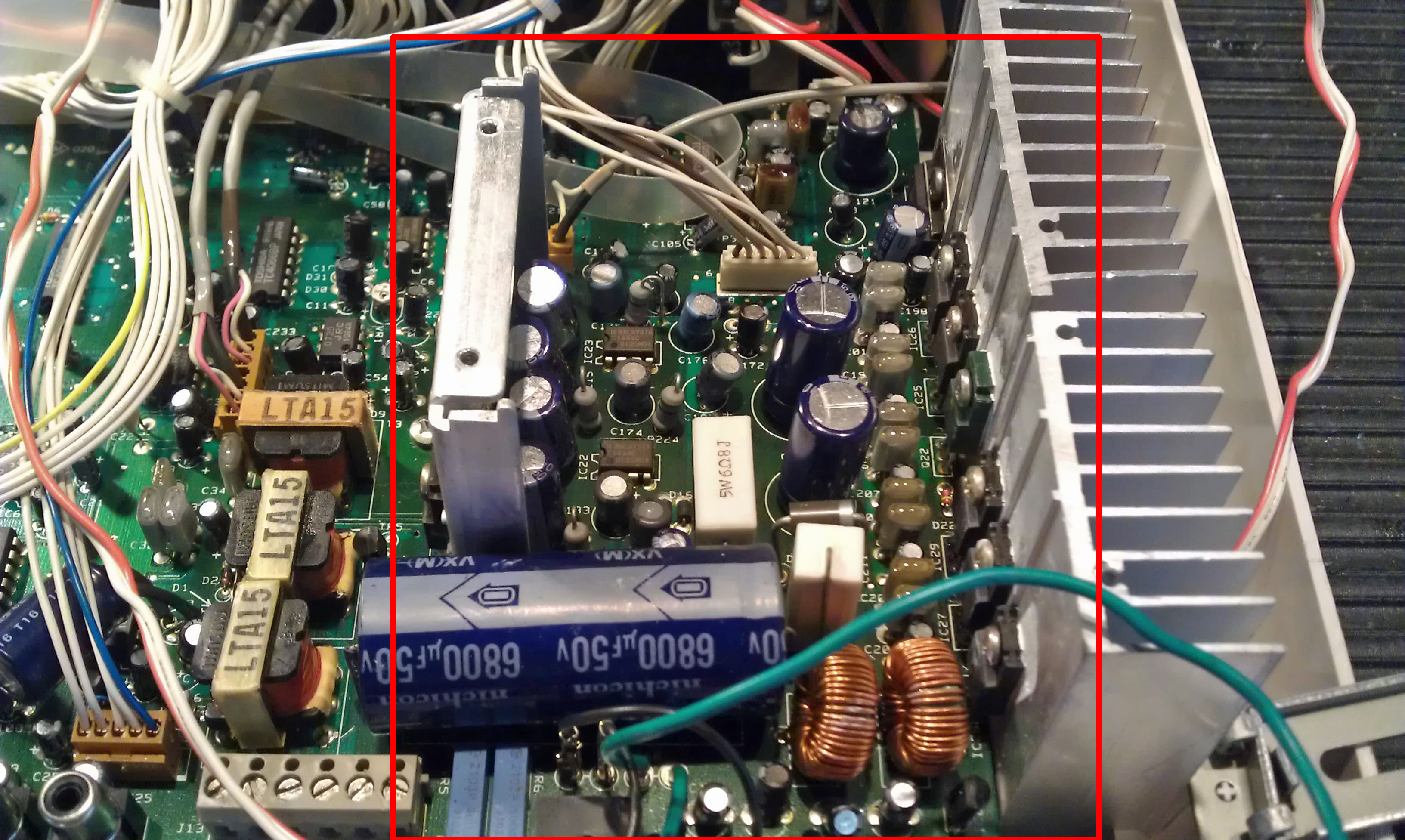
Usually after 10-12, years some of the components in the power supply will begin to fail, which will cause operational problems with the system. What we have seen as the progression of these problems is:
There will be a slight increase of “hum” at the master station and on the remote speakers. This is not too noticeable and it seems to be overlooked by most homeowners.
Then there will we some random “static” or “crackling” noises heard throughout the system. This will be noticeable but it occurs infrequently at first, then it happens more and more often. At this point the system is just at the verge of failing. There are typically two ways the problem will progress from this point.
One way is the long slow version which can take months or even years for the IM5006 to fail.
The other, more common way is for something to push the IM5006 into a dramatic failure, such as a power outage in the home or the circuit breaker being turned off then back on.
We find that a power outage will typically push the IM5006 over the edge into complete failure. Complete failure on a IM5006 is really dramatic, and will cause the system to go into what we call the “alarm noise” failure. This is a loud, pulsating sound for the system that is impossible to stop unless you turn the circuit off that powers the IM5006 master.
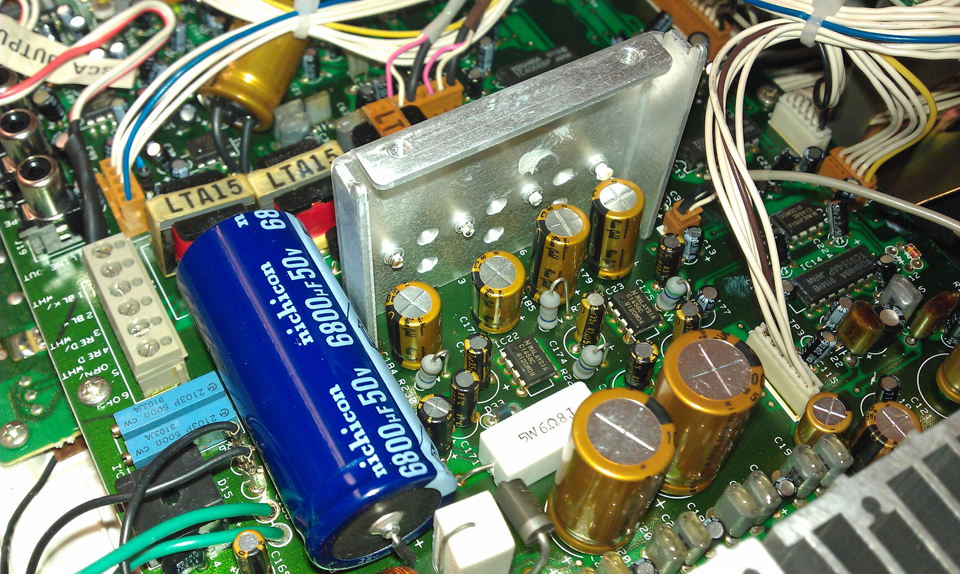
The solution for this type of failure is to have the IM5006's power supply circuit board rebuilt. This involves replacing 24 different components on the main circuit board.
PROBLEM #2: Failed Remote Station
This is becoming a more common problem as the IM5006 systems age. Until recently we had not seen any real number of failed remote stations, but within the past 2 years, we are seeing more and more.
Because of the complexity of the design of the IM5006 a failed remote station can cause the entire system to become non-operational. This is because the remote stations share common power and common communication lines with each other and the IM5006 master station.
What we typically find is that all of a sudden the complete system will stop working or sometimes just a single function will no longer work. These problems can all be caused by a single, failed remote station.
Finding a failed remote station requires troubleshooting the system in the location where it is installed.
Repairing defective remote stations is not a very practical thing to do since there are lots of good used circuit boards available at this time.
PROBLEM#3: Failed Patio Stations
The control panel covers on the IS519 and IC502W Patio stations will fail due to exposure of sunlight over many years. While this would seem to be mostly a cosmetic issue, it will lead to a more serious failure over time.
When the control panel cover begins to fall apart, it creates places where water can get into the station. This will cause the circuit board inside the station to get wet and this will lead to corrosion on the circuit board. The corrosion will damage the circuit board, causing the station to fail.
Replacement circuit boards for the IS519 and IC502W are no longer available from NuTone, and like all discontinued outdoor equipment, any leftover stock is long used up.
The circuit boards in these 2 models of remote station are exactly the same as their indoor counterparts except in 2 ways. The shape of the indicator LED's are round instead of rectangular and the circuit boards are sprayed with a special sealant to help protect them for outdoor duty.
We have been successful in performing LED transplants to modify circuit boards from indoor stations to fit outdoor station grills. The sealant is commonly available and simple to apply to help weather proof the boards.
This leaves the problem of the failed control panels, which we are currently working on a solution for.
 Cindy & Christopher
Problem #4: Lightning Damaged IM5006 Master Stations
Lightning can cause what I call "Unnatural Damage". Lightning will cause components to fail that normally would never fail and this causes unusual operational problems.
Last week I had a customer send in a IM5006 from Florida with what seemed like a typical power supply failure. After the power supply was rebuilt the IM5006 was connected to our "bench" intercom system setup. This setup consists of three IS515 inside remote stations a IS69 door speaker and a IS519 Patio Station.
As we worked through the operational check-out for the IM5006, we found many operational problems that were not related to the failed power supply.
These problems were:
1. The master station could communicate with the door station, but the remote stations could not.
2. The remote stations could communicate with each other, but not with the master station.
3. "ALL-CALL" would connect the master to the remote stations, however the communication was just one-way, from the master to the remote stations, but not from the remote stations to the master.
4. When the Chime Module was activated, the radio became muted but not chime sounds could be heard. (it was not a bad chime module).
All of these problems pointed towards the Control Circuit Board. After measuring voltages to the board, which were fine, the board was swapped with a know good board to make sure we were on the right path, we were.
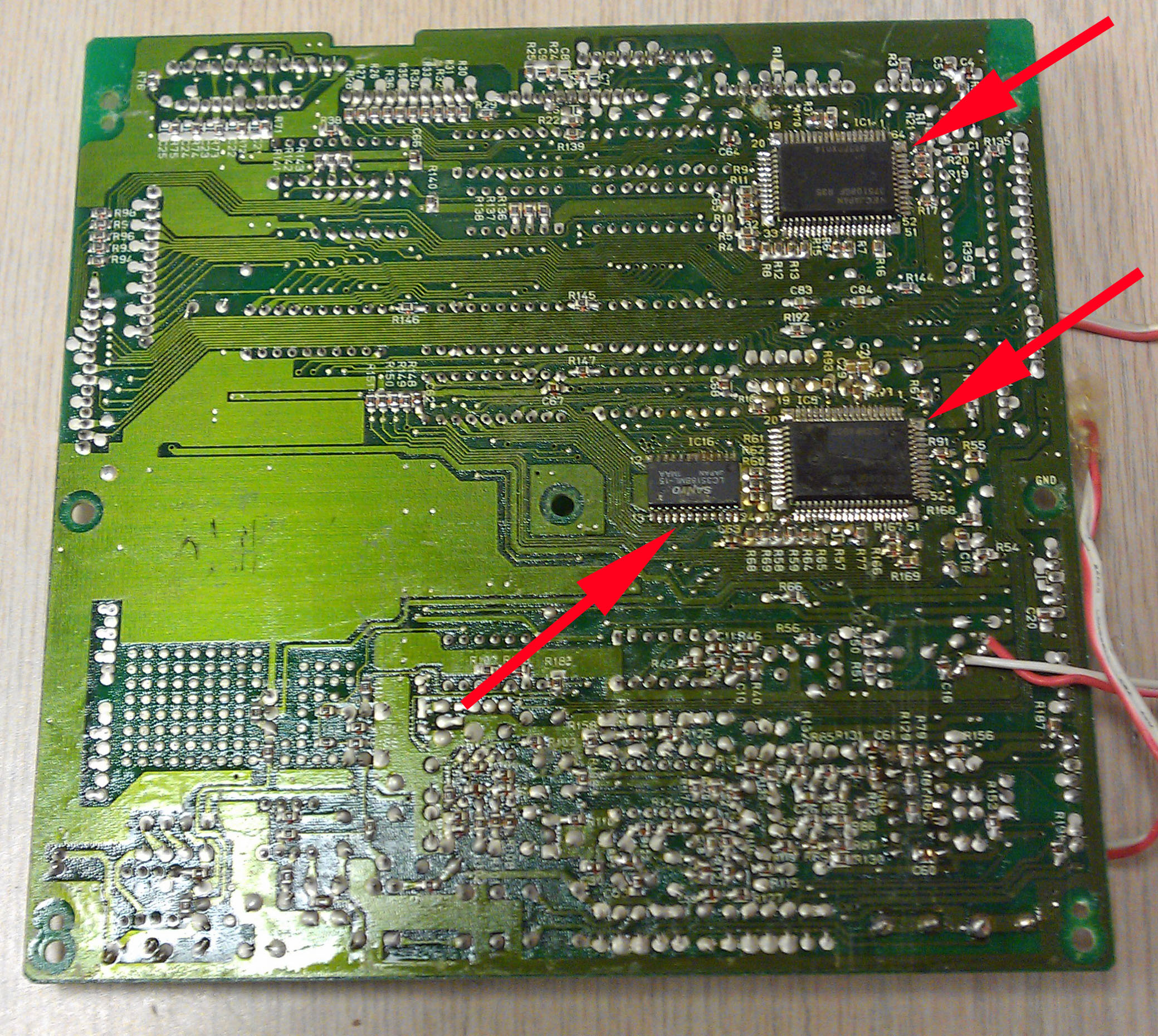
The Control Board in a IM5006 is a very complicated design and it requires specialized equipment and some skill to test and repair. It may look like an ordinary board until you flip it over and find the two microcomputer chips on the back of the board.
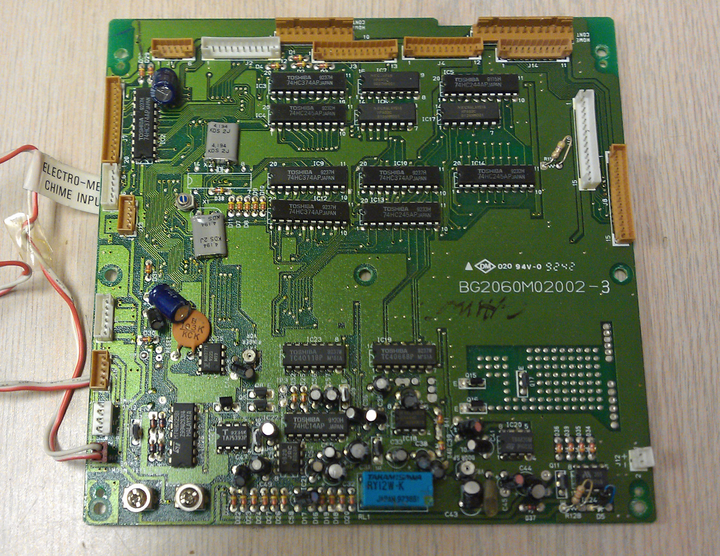
These microcomputers are the engine that drives the IM5006 along with many other IC's that perform the actual "work" that makes the IM5006 operate correctly. Normally these types of IC's would never fail on their own, but when you have a lightning damaged unit anything is possible.
For this particular IM5006 the problems were solved by replacing several of the supporting IC's on the control board, the microcomputers were undamaged.
If the microcomputers had been damaged, the complete board would have to be replaced.
Cindy & Christopher
Are You Living with a Discolored and Yellowed IM5006 Master Station?
Here's a link to our trial method which reverses the yellowing process.
Please read through the entire atricle, there's a lot of pictures, the IM5006 are at the end of the article.
Reader Comments (1)
Hi, it is interesting to read your experience. I have a circa 1992 IM 5006 and it started that loud howling after turning off the main circuit, then the remote stations xformer failed. I replaced all ~200 capacitors (from Mouser) on the main board, control board and a small board mounted at the rear / bottom of the unit.
I had a single 'miss' on 1 of the capacitors: whose value I didnt document when I removed the caps on that board.
Can you tell me the value of Capacitor C-58? I believe it is a 10 microfarad x 16 volt but want to be sure!
Many thanks for any help you can provide.