NuTone Model IM4006 Radio Cassette Intercom
 Saturday, January 5, 2013 at 11:57AM
 Exciting news for the music lover and those with discriminating audio tastes! The finest audio you can imagine in a home-communication system is yours. . . from NuTone.
The IM4006 was introduced in 1986 and quickly became the most popular music intercom system that NuTone had ever made. The IM4006 was based on a new platform that began with the IM3003 in 1984 and that platform design was used through the end of 2006.
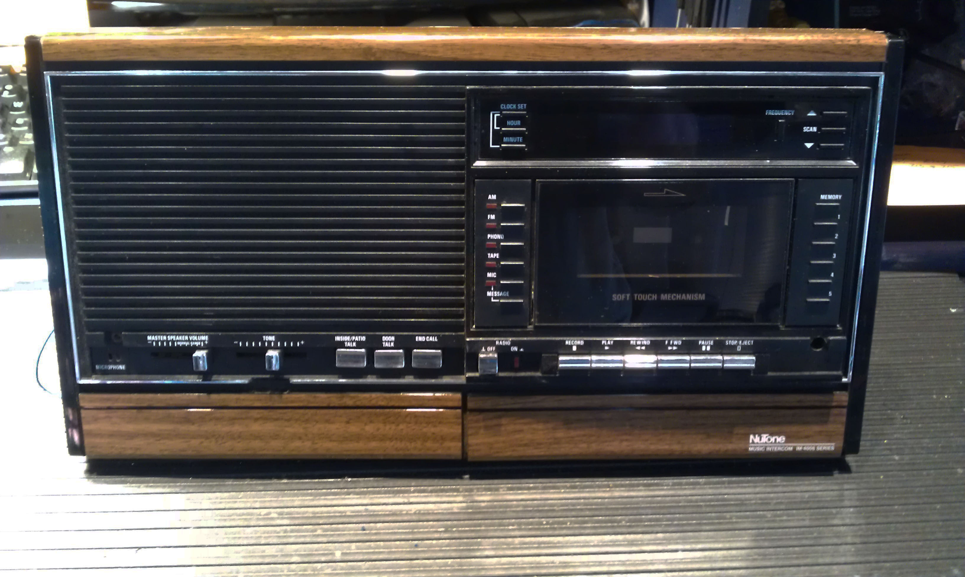
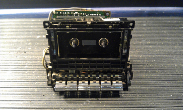
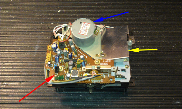
The IM4006 featured a cassette tape recorder that doubled as a family message center, allowing any user to leave a voice message for family members to listen to.
The IM4006 was the very first model of music intercom to feature a true digital radio tuner with electronic scan tuning, 10 programmable radio station presets and a digital clock and radio frequency readout.
Since the IM4006 is a 6-wire system, it features “hands-free” reply intercom functions and remote stations including a “Privacy” button to block unwanted listening into that room.
The standard IM4006 was designed to accommodate up to 9 remote stations, but with the IA410 Expansion Kit, the maximum number of remotes increased to 20.
The IM4006 was a very reliable system right from the beginning with the exception of a new type of wire that NuTone introduced for the IM4006. The new wire was NuTone's IW6R, the “R” stands for ribbon.
This ribbon wire was a attempt to make the installation of the IM4006 easier and quicker, the exact opposite is what really happened.
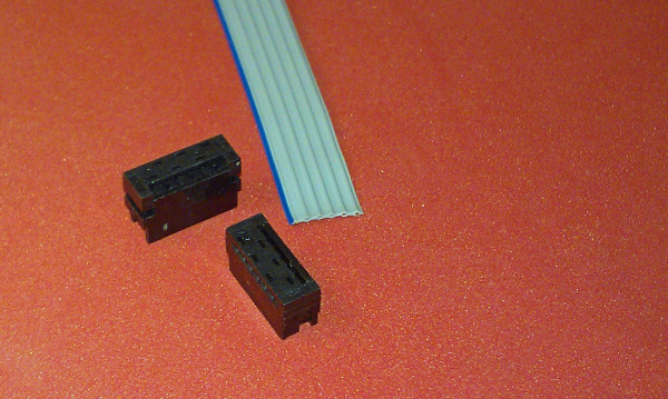
The original IW6R was a flat, 6-wire ribbon cable that had solid wire inside the ribbon. The insulation that made up the ribbon was thin and it could be easily damaged during the pre-wire of a new home.
Installers were accustomed to IW6 cable, which is strong and pulls easily through pre-drilled holes in construction framing. IW6R ribbon wire is almost 1 inch wide and unless the pre-drilled holes are extra large, the edges of the cable will be damaged when the cable is pulled through the holes. It was not uncommon to have several cable runs in a single house have damaged wires.
The IW6R used crimp-on connectors that were included with each remote speaker. These connectors were to be crimped on to the ends of the IW6R cable when the system was trimmed out.
Installing the connectors required reading the directions (not a popular thing for installers to do) and some amount of finesse in preparing the cable and crimping the cable (also not a popular skill with installers).
A well-done intercom trim-out could be completed in half the time compared to using cable with indivisible wires.
Another feature that made the IM4006 so popular was starting in 1986, NuTone offered a “Life-Time” Warranty on all of their intercom systems. This warranty included Parts, Labor and In-Home Service for any problem with the systems. I personally performed many hundreds of warranty calls which were just to replace crimp-on connectors.
The IW6R cable was modified to use stranded wire in the cable which eliminated the potential of the crimp-on connector not making a good connection to the wire. It did not solve the “installer skill” issue. Around 1991 NuTone abandoned IW6R cable and the newly revised IMA4006 went back to standard IW6 cable with its individual wires fastened to screw terminals.
While NuTone choose to only label this model as the IM4006 and later the updated version became the IMA4006, there are actually 3 different variations if you look at the circuit board changes from 1986 through 1996.
The breakdown for the 3 variations is roughly:
1986 – 1987 Original Version Boards
1988 – 1991 1st revision of amplifier/power supply, intercom control and master control boards.
1992 – 1996 2nd revision of amplifier/power supply, intercom control, master control, terminal board and function selector boards.
There is not a lot of interchangeability between the 3 variations listed above. Intercom control boards can be used on all 3 variations, but amplifier/power supplies and master control boards cannot, and should be considered as “sets”.
The boards and assemblies that remained mostly unchanged throughout its production were the radio tuner, memory/display, cassette player & pre amp boards. These parts are interchangeable on all versions made from 1986 through 1996.
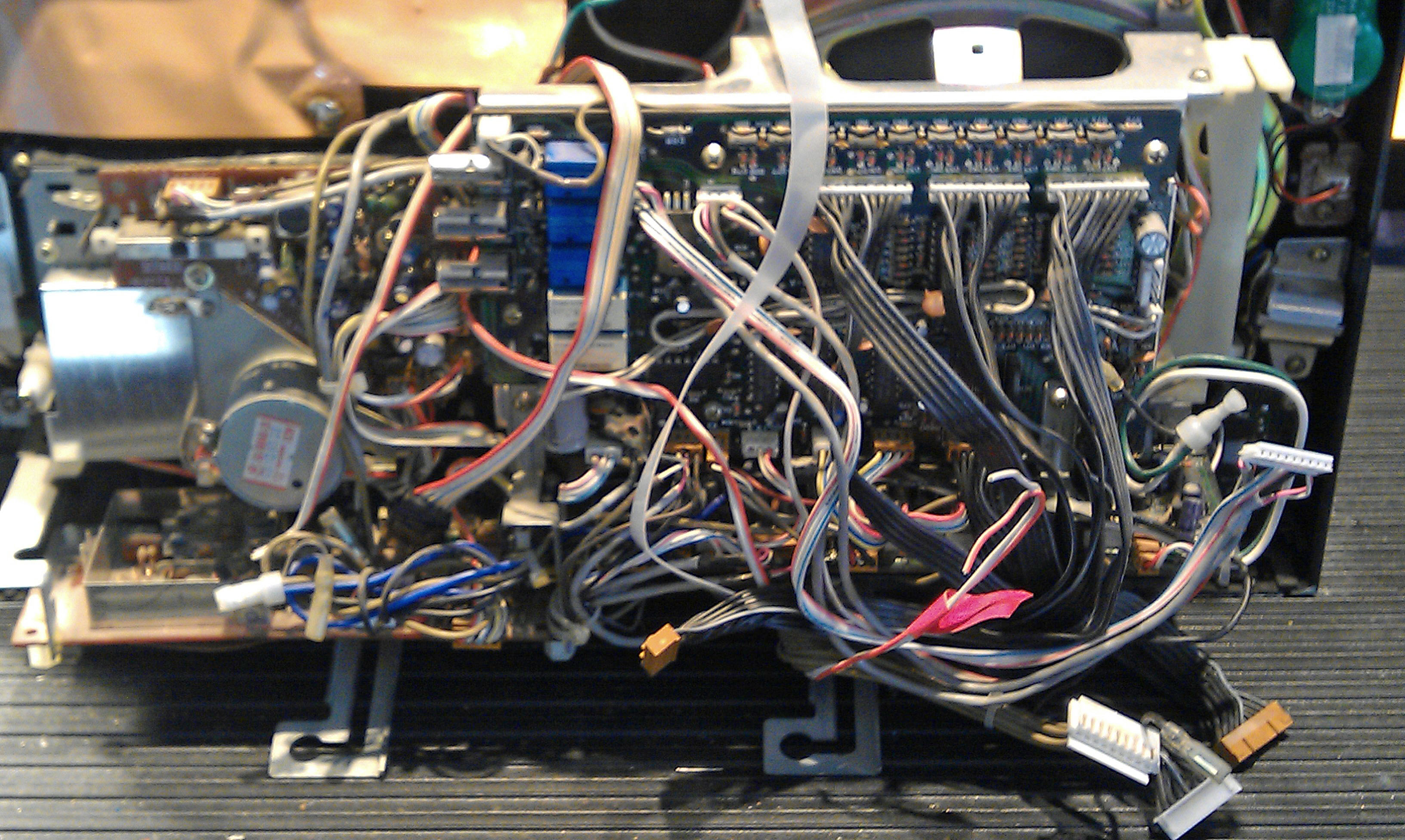
(The IM4006 is a complicated unit with many circuit boards and interconnection cables)
See all of the IM4006 pictures
Make an Intercom Service Request
 Cindy & Christopher
Common Problems with the IM4006 and IMA4006:
Power Supplies: As with all mid 1980's NuTone Intercom systems, failing power supplies are the most common problem. The faint amount of background “hiss” on the system that was always present will gradually turn into a “hum”. The hum will become louder and louder and finally become a “buzz”.
The radio will be effected, as will the built-in door chime, the intercom functions will likely also fail. If this is left unrepaired for a long period of time (months to years) it will eventually cause damage to the amplifier.
Fortunately, the power supply and amplifier in an IM / IMA4006 is based on the same design as the IM3003. The version in the 4006 has a few additional components, but it's basically the same. While rebuilding the power supply is simple, getting it out of the master is not so simple.
The IM / IMA4006 is built-up from 6 separate circuit boards plus the cassette player assembly. There are dozens of interconnection cables which plug the different boards into each other. The power supply and amplifier board is buried way down inside the master and most of the master has to be disassembled to get it out. This is not a good unit for the amateur to learn on.
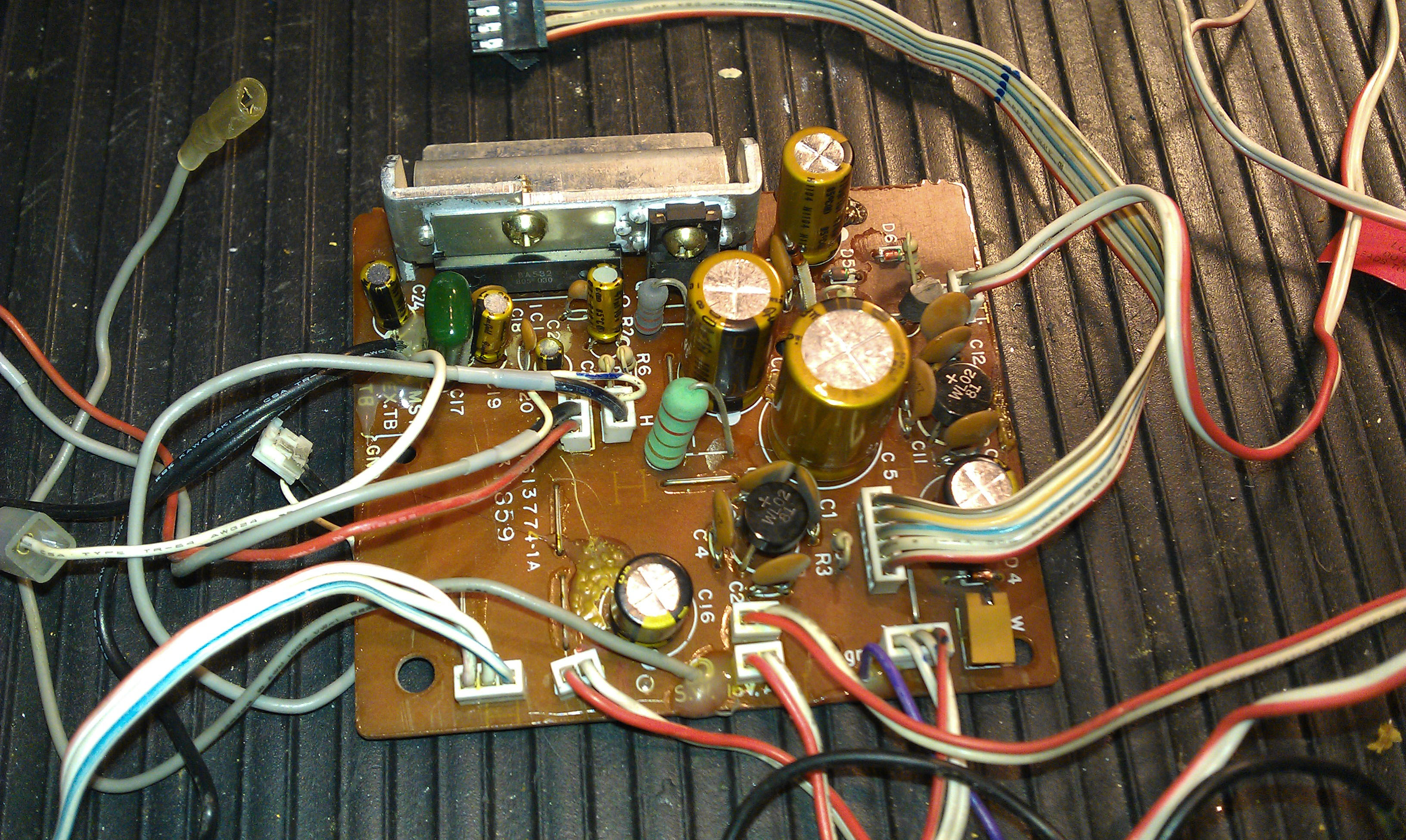
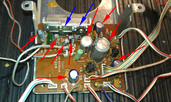 (red arrows are capacitors, blue arrows are amplifier IC and voltage regulator IC)
Once the power supply is removed, there are just 9 capacitors that need to be replaced.
Part 2 - Secondary Power Supply Circuits in your IM4006 and IMA4006
One overlooked fact about NuTone IM4006 and IMA4006 Intercom Master Stations is that there are two additional power supply circuits which are located on the Master Circuit Board and the Control Circuit Board.
When repairing an IM4006 or IMA4006, both of these boards should be rebuilt along with the main power supply and amplifier board. If these secondary circuits are left untouched, additional faults will occur in the future and the intercom will need further repair.
Both of these circuit boards have their own independent power supply circuits with Linear Voltage Regulators at the heart of each circuit.
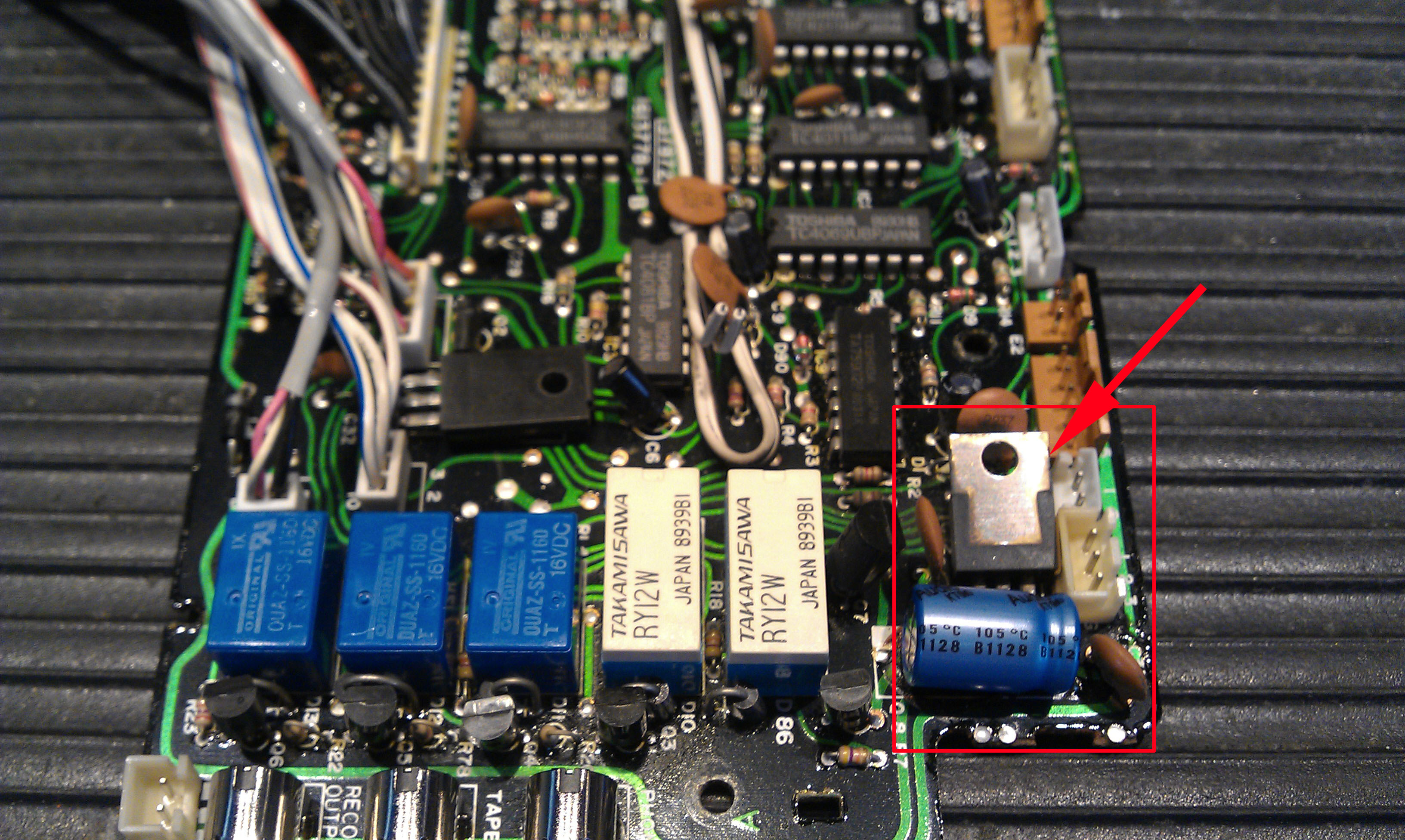
The Control Board is a simple circuit with just a few capacitors that will need to be replaced.
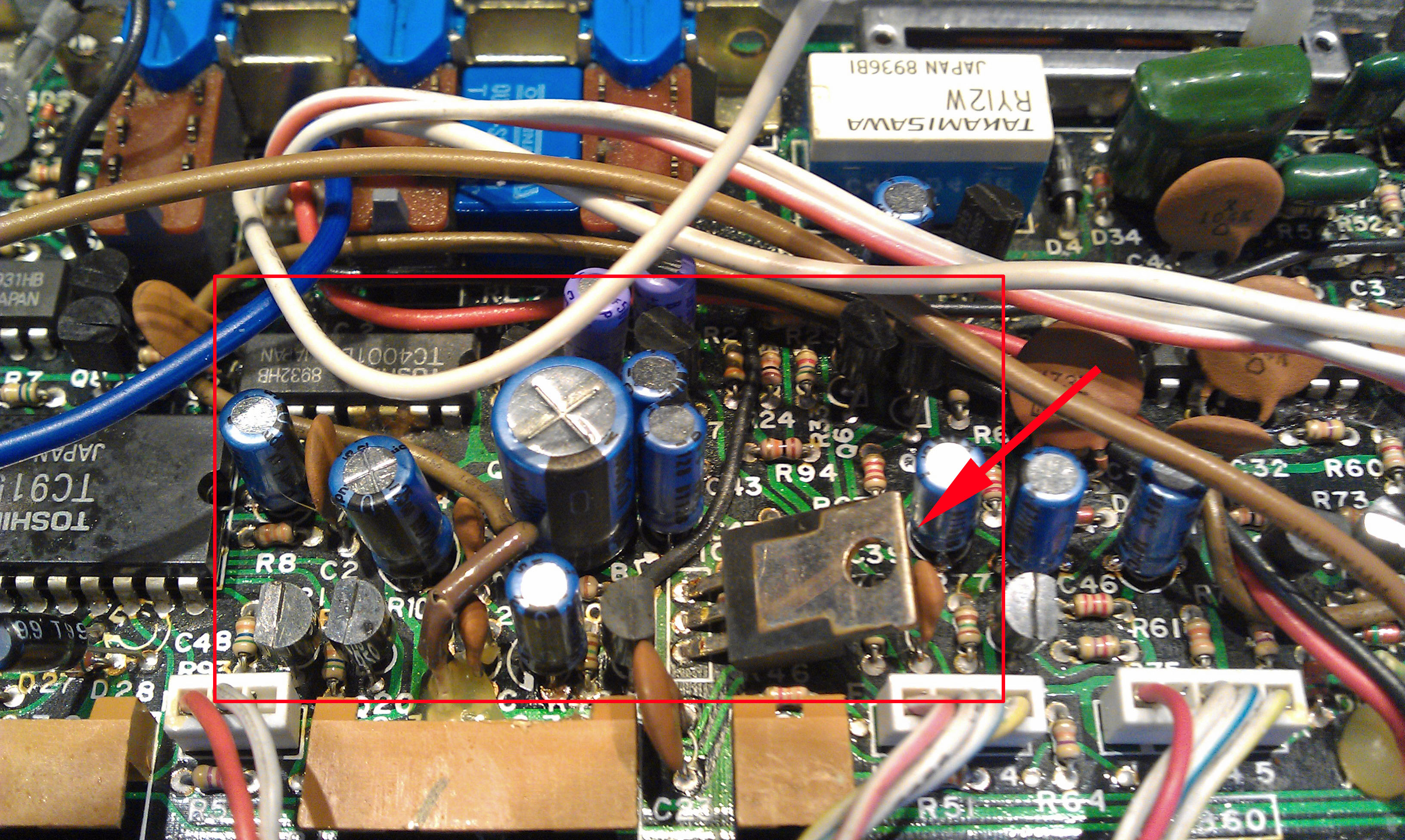
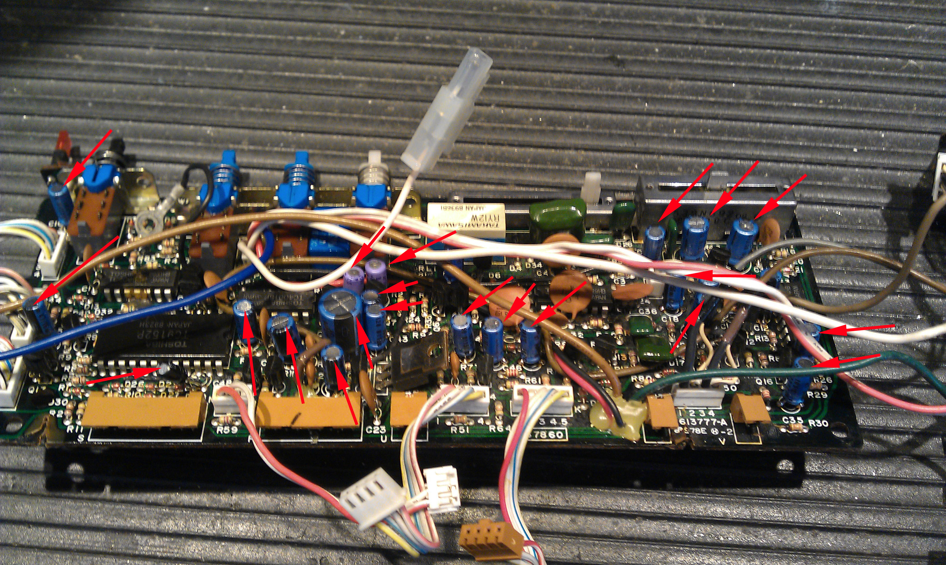
The Master Circuit Board is a double-sided circuit board which is packed with components, making it much more difficult to work on. There are 21 capacitors which will need to be replaced in order to rebuild the board completely.
The circuit board fabrication in the IM4006 and IMA4006 is typical for a mid 1980's design, which is to say, less than perfect by today's standards. Automated soldering from the 1980's is not top quality, and it results in what appears to be many dull, thinly solder joints.
These types of solder joints do not de-solder very well and often it is necessary to first resolder them by hand before the de-soldering is done.
Another consideration is the double-sided circuit board. These types of boards require specialized tools to de-solder components correctly without damaging the circuit traces and solder pads. If the de-soldering is done incorrectly, the pads and traces can become detached from the boards surface and tear off.
Because of the limited amount of room to work in, repairing the damaged pads and traces is very, very diffcult, if even possible.
Rebuilding these types of boards is not for the inexperienced, first timer. The risk of ruining the board is very high and since replacement boards are hard-to-find and expensive, caution is required.
PART 3: Terminal Boards
In the past few months, I have seen unusual problems with the original style terminal board from the NuTone IM4006 series Radio Intercom.
The original version of the IM4006 are the models that use the flat IW6R six-conductor ribbon wire with the crimped-on connectors. The matching terminal boards are referred to as “amp” style terminal boards.
The terminal board is a simple design and for the most part, it has always been a trouble free part of the system.
Recently I have seen two terminal boards with the exact same problem. The symptoms of the problem are that the remote stations do not work correctly. These affected stations will play music and can put the IM4006 system into “intercom mode” but there is no voice communication and the end call feature doesn't work.
These symptoms may seem typical for an IM4006 system with major master station problems, however in both cases, the master station and the majority of the remote stations worked correctly. Remember that almost all of the IM4006 system controls are located in the Master Station, not in the remote stations.
These symptoms can also mimic problems from damaged wiring or improperly installed crimp connectors at either end of the IW6R ribbon cable. Troubleshooting this type of problem in the field can be confusing and will likely be time consuming.
Troubleshooting this problem on the repair bench is easier because all of the remote stations' wiring has been eliminated as a source of the problem and typically just one remote station is used for testing. The single remote station can be connected to each terminal board connection one at a time, and then checked for proper functionality of that terminal board connection.
The cause of this new problem is caused by a failure with some of the electronic components on the terminal board.
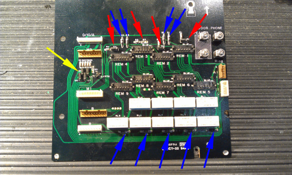
(red and yellow arrows are transistors, blue arrows are diodes)
The IM4006 terminal board has 9 amp connectors, one each for the 9 remote stations that an IM4006 system can have. Each of the 9 terminal board connections include as part of the circuit: 1- Transistor, 1- Diode, 1- Resistor and 1- Relay. This means that the terminal board contains a total of: 9- Transistors, 9- Diodes, 9- Resistors and 9- Relays.

(red arrows show where trasistors have been removed)
The problem I observed was caused by failures with some of the transistors and diodes which drive the control relays on the terminal board.
In one case there were 2 terminal connections that were effected (remote stations #3 and #9). In the other case there were 6 of the 9 terminal connections that had failed.

(removed defective transistors and diodes)
Replacing the failed components is a straight forward task and after the repair was complete, everything worked correctly again. The real question is: why did this failure happen?
I will be looking into the possible causes of this type of failure. More to come on this topic.
 Cindy & Christopher
Does the Display on Your IM4006 Show the Correct Reading?
While most IM4006's and IMA4006's have normal and expected problems, every once in awhile a more unusual problem turns up.
This IM4006 was delivered with a list of problems from the home owner, which included "AM Radio doesn't work".
The pictures tell the entire story.
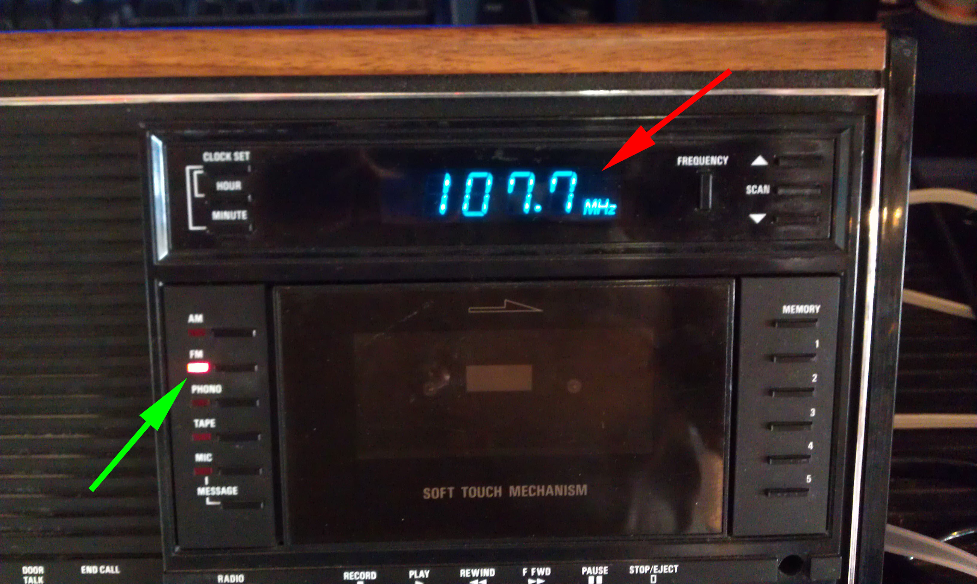
If you look carefully, you will see that the Red FM LED is lit and the Display shows the FM Radio Station Frequency. This is as it should be.
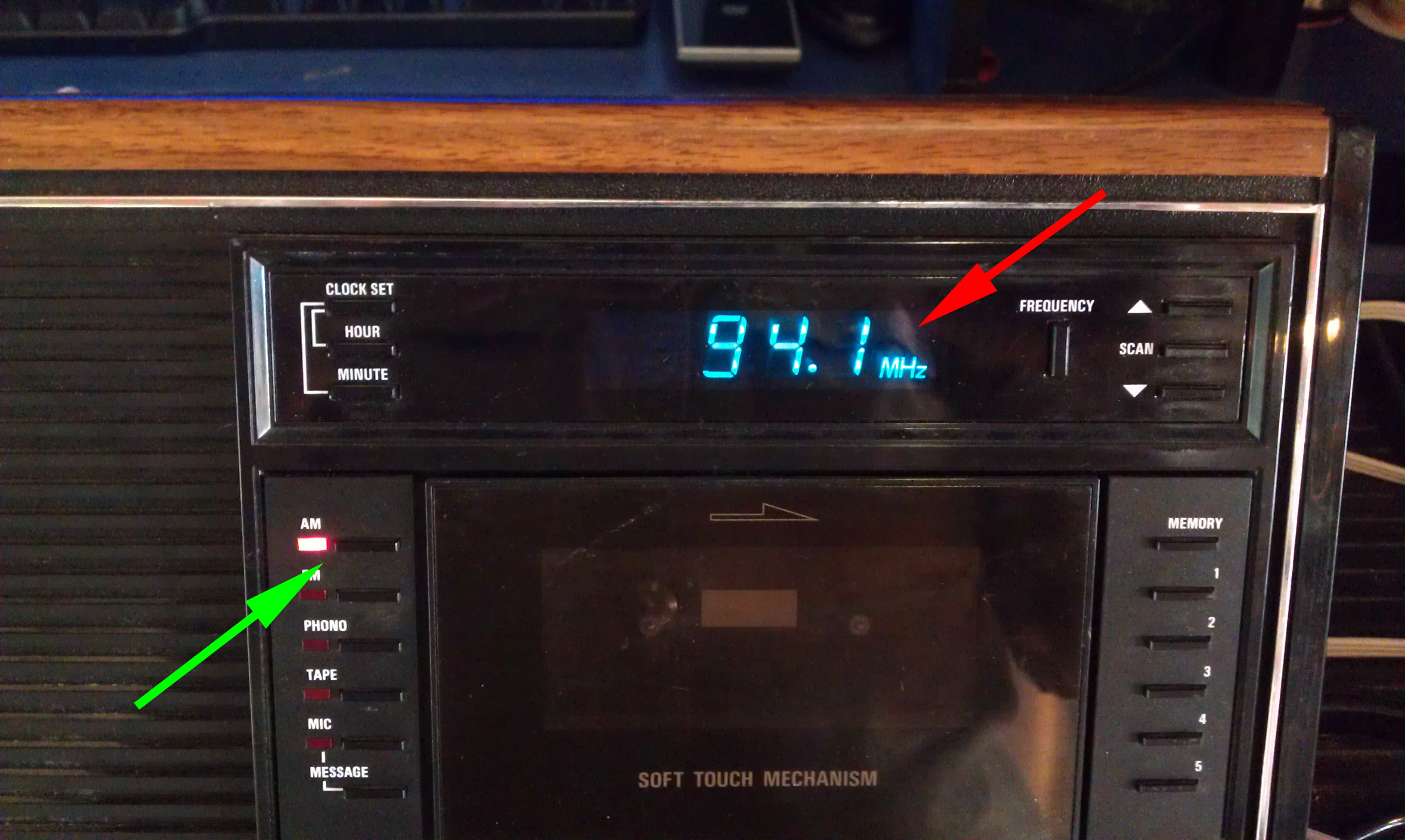
Now look very carefully at this picture. . . can you see what the problem is?
The Red AM LED is lit but the Display still shows an FM Radio Station Frequency in the readout.
It might seem that there must be a problem with either the Display Circuit Board or possibly with the Tuner Circuit Board, but that's not where the problem originates from.
This type of problem originates from the Master Control Circuit Board. This board manages all of the different Audio Inputs sources that are built-in to the IM4006. When someone pushes a source selection button (AM - FM - Phono - Tape) the Master Control board enables the circuits to that source.
When there is a flaw in the Control Circuit, the source will not be switched correctly and the Mater Station will not work correctly.
Another example was another IM4006 which worked correctly except there wasn't any play-back audio from the cassette player. After eliminating the cassette player as the source of the problem, we determined that the Master Control Board was not turning on the input pin of the IC that received the audio from the cassette player.
If your IM4006 is in need of Repair, Use thin Link to Contact Us.
 IM4006,
  IW6,
IW6,  IW6R,
IW6R,  cassette tape recorder